LN2 System
The GEARS detector requires uninterrupted LN2 cooling to maintain operation, and therefore an automated LN2 control system is used to periodically fill the detector dewar at times that are defined in a user-created schedule file.
The GEARS LN2 system is also used to supply LN2 to HPGe detectors in the test stand, called Compton Suppressed Spectrometer or CSS stand, located next to the GEARS station. While the operation of the CSS test stand is beyond the scope of this documentation, the diagrams show its existence and connections to the shared control systems.
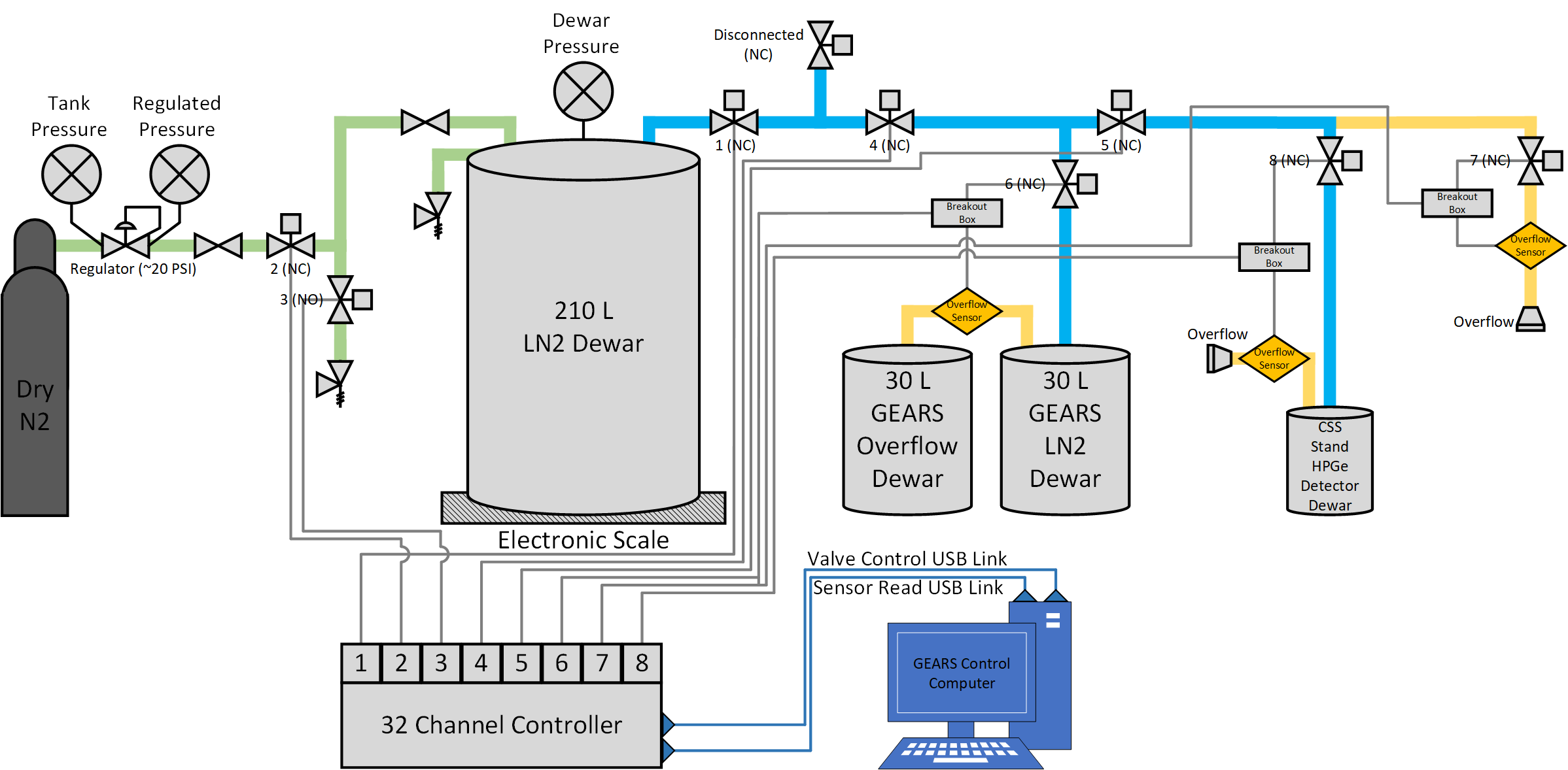
Diagram of LN2 System Connections
The major components of the GEARS cooling system are a 210 L LN2 dewar (that is manually filled when empty), a dry nitrogen gas bottle that is used to pressurize the system when filling GEARS, a 30 L ORTEC LN2 dewar that is directly coupled to the GEARS detector cryostat, a series of valves that control LN2 flow, as well as a scale readout of the 210 L dewar and a set of overflow sensors that report to a 32 channel valve controller. A block diagram of the entire system is shown below in Figure 1.
LN2 Flow Control
The valves used to control LN2 flow as well as the overflow sensors that provide feedback on fill status are operated by a 32 channel LN2 controller. This controller operates via commands exchanged over a USB link with the GEARS control computer (using the LN2 user account) or manually using an array of switches on the front panel.
Note: The overflow sensors use green or red LEDs and a voltage divider circuit to read the presence of LN2. When an LED is cooled by LN2, its forward voltage increases linearly until it reaches a maximum value when the LED is submerged in LN2. The voltage across the LED is read by the voltage divider circuit and an ADC built into the 32 channel controller. When the measured voltage passes a user-specifed threshold defined in the configuration file, the LN2 fill will end.
LN2 Server and Client Programs
GEARS LN2 control runs on a message queue manipulator client / server system implemented via linux-based msgtool. A server running on the GEARS compute receives commands from a client program (also running on the GEARS computer) to start and stop fills. The client commands that can be used are listed below.
- begin -- Begins the run. The LN2 filling process will occur based on the schedule defined in schedule.dat.
- start -- Same as above.
- end -- Ends the run. If currently filling, ends the filling process.
- stop -- Same as above.
- fill detector_name -- Starts the dewar filling process immediately for the detector with name detector_name defined in schedule.dat.
- stopfill -- Stops any fill which is currently in progress, and continues the run normally.
- time -- Shows the time elapsed since the last filling operation.
- on X -- Manually turns on the DAQ switch X, where X is an integer (from 0 to 31 on the DAQ controller).
- off -- Manually turns off all DAQ switches, closing all valves.
- measure X -- Shows the voltage reading on DAQ channel X, where X is an integer (from 0 to 31 on the DAQ controller).
- table -- Shows recent sensor data in a table format.
- save filename -- Saves recent sensor data to a text file with name specifed by filename.
- exit -- Ends the run and exits the LN2_server program.
- quit -- Same as above.
Run parameters can be modified by editing the text file parameters.dat in the folder ~/LN2_32channels/current directory of the LN2 user account on the GEARS control computer. Parameters may be edited while the program is running, in which case they will be applied on the subsequent run.
Typically, LN2 server runs in the virtual terminal accessible by Ctrl+Alt+F2 on the GEARS computer, while the client is run in the virtual terminal accessibe by Ctrl+Alt+F3. In non-standard operation the server can be started remotely using nohup and &, while client can be access for control of the server via ssh. The server opens a lock file on startup to assure that only a single server is operational at the time. Improper shutdown of the server may not remove the lock file. If lockfile exists, it will prevent startup of the LN2_server.
The Fill Schedule
Automated filling procedures can be written into a schedule.dat file on the GEARS computer. This allows for automatic and uninterrupted operation of the system as long as there is LN2 present in the 210 L dewar. The schedule.dat file can be found in the ~/LN2_32channels/current directory of the LN2 user account on the GEARS control computer. A default schedule.dat file is shown below.
GEARS_monday_precool,valve[0,1,2,3,4,6],overflow_sensor[6],time[monday,12:00]
GEARS_monday,valve[0,1,2,3,5],overflow_sensor[5],time[after_entry,GEARS_monday_precool]
GEARS_friday_precool,valve[0,1,2,3,4,6],overflow_sensor[6],time[friday,12:00]
GEARS_friday,valve[0,1,2,3,5],overflow_sensor[5],time[after_entry,GEARS_friday_precool]
According to the schedule posted above, the GEARS detector is filled every Monday and Friday at noon, and each fill is preceded by what is called a “precool”. Precools are performed to cool down all the plumbing between the 210 L dewar and the detector to LN2 temperatures. During this time, a large volume of LN2 is converted to gas and exhausted into the laboratory space, this is done to limit the amount of warm gas injected into the GEARS dewar during a fill.
Scale and Overflow Readouts
The weight of the 210 L LN2 dewar is read out from a large platform scale that the dewar is placed on. The scale sensor provides a voltage signal proportional to the mass which is read out by National Instruments USB 6008 data acquisition card operated by nidaqmxbase software modified to compile on Centos 7 distribution. This signal is calibrated to weight. Both the weight of the dewar as well as the status of the LN2 overflow sensors are routed through influxDB and to a Grafana UI that can be viewed by clicking the LN2 button on the Links page. The GEARS computer software for scale redout is operated as as a linux service (specifically scale.service), is activated at boot, and controlled by systemctl.
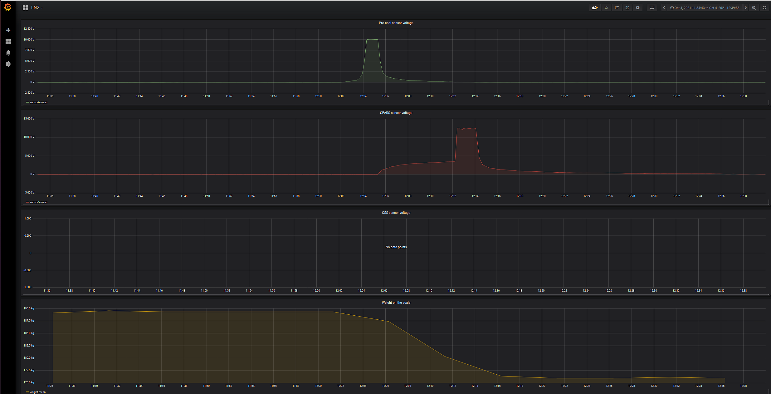
The dashboard named LN2 in Grafana running on the GEARS computer displays the status of the three overflow sensors in use as well as the status of the scale. An example of a typical GEARS fill operation can be seen below in Figure 2.
Note: A username and password are required to view the Grafana page reporting status of the LN2 sensors and the scale readout.